I received an email from the director of
Center for Advanced Brain Imaging Chris Rorden, PhD, who asked some help regarding clipping plane for a raycasting volume in GLSL. He is also the creator of the free
MRIcroGL a program designed to display 3D medical imaging using computer's graphics card.
As I had no experience with volumetrics and raycasting, in the (helping) process I learned a lot of how this stuff actually works.
So together we came up with this cool GLSL volume clipping method (Chris did the most of it hehe). Chris also suggested that the solution would be open source, so I could share it on my blog to help others.
I am not sure if we were not reinventing the wheel here, but I could not find "shader based clipping plane thing" in the web anywhere.
so the fragment shader goes like this:
uniform float azimuth, elevation, clipPlaneDepth; //clipping plane variables
uniform bool clip; //clipping on or off
varying vec3 pos; //gl_Vertex.xyz from vertex shader
// Single-Pass Raycasting at The Little Grasshopper
// http://prideout.net/blog/?p=64
struct Ray
{
vec3 Origin;
vec3 Dir;
};
struct AABB
{
vec3 Min;
vec3 Max;
};
bool IntersectBox(Ray r, AABB aabb, out float t0, out float t1)
{
vec3 invR = 1.0 / r.Dir;
vec3 tbot = invR * (aabb.Min-r.Origin);
vec3 ttop = invR * (aabb.Max-r.Origin);
vec3 tmin = min(ttop, tbot);
vec3 tmax = max(ttop, tbot);
vec2 t = max(tmin.xx, tmin.yz);
t0 = max(t.x, t.y);
t = min(tmax.xx, tmax.yz);
t1 = min(t.x, t.y);
return t0 <= t1;
}
//polar to cartesian coordinates
vec3 p2cart(float azimuth,float elevation)
{
float pi = 3.1415926;
float x, y, z, k;
float ele = -elevation * pi / 180.0;
float azi = (azimuth + 90.0) * pi / 180.0;
k = cos( ele );
z = sin( ele );
y = sin( azi ) * k;
x = cos( azi ) * k;
return vec3( x, z, y );
}
void main()
{
vec3 clipPlane = p2cart(azimuth, elevation);
vec3 view = normalize(pos - gl_ModelViewMatrixInverse[3].xyz);
Ray eye = Ray( gl_ModelViewMatrixInverse[3].xyz, normalize(view) );
AABB aabb = AABB(vec3(-1.0), vec3(+1.0));
float tnear, tfar;
IntersectBox(eye, aabb, tnear, tfar);
if (tnear < 0.0) tnear = 0.0;
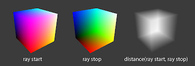
vec3 rayStart = eye.Origin + eye.Dir * tnear;
vec3 rayStop = eye.Origin + eye.Dir * tfar;
// Transform from object space to texture coordinate space:
rayStart = 0.5 * (rayStart + 1.0);
rayStop = 0.5 * (rayStop + 1.0);
vec3 dir = rayStop - rayStart;
float len = length(dir);
dir = normalize(dir);
//now comes the clipping
if (clip)
{
gl_FragColor.a = 0.0; //render the clipped surface invisible
//gl_FragColor.rgb = vec3(0.0,0.0,0.0); //or render the clipped surface black
//next, see if clip plane faces viewer
bool frontface = (dot(dir , clipPlane) > 0.0);
//next, distance from ray origin to clip plane
float dis = dot(dir,clipPlane);
if (dis != 0.0 ) dis = (-clipPlaneDepth - dot(clipPlane, rayStart.xyz-0.5)) / dis;
if ((!frontface) && (dis < 0.0)) return;
if ((frontface) && (dis > len)) return;
if ((dis > 0.0) && (dis < len))
{
if (frontface)
{
rayStart = rayStart + dir * dis;
}
else
{
rayStop = rayStart + dir * dis;
}
dir = rayStop - rayStart;
len = length(dir);
dir = normalize(dir);
}
}
// Perform the ray marching
vec3 step = normalize(rayStop-rayStart) * stepSize;
float travel = distance(rayStop, rayStart);
for (int i=0; i < MaxSamples && travel > 0.0; ++i, rayStart += step, travel -= stepSize)
{
// ...lighting and absorption stuff here...
}
}
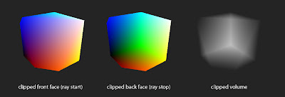
here are some illustrations:
volume clipping with azimuth 124°, elevation -44° and clipPlaneDepth 0.2 values
and a video of it in action


