Yep, I haven`t been very active blogger lately.
I am very glad that company I am working for brought me to Amsterdam to Blender Conference this year. I even did a presentation there together with my colleague Michael Otto about GLSL shaders in Blender Game Engine. And for the presentation purposes I decided to demo my water/underwater shader there.
Just before the presentation I managed to tune up the shader and the scenery a bit.
so the changes since last update are:
- projected grid approach for the water surface (lousy implementation)
- per-vertex displacement mapping for waves
- basic but effective shoreline detection for water surface and ground
- added some subtle cloud layer and stars in the skies
yet to be done:
- fixes on inconsistencies
- better and procedural wave propagation model
- focus to underwater visuals
- better camera transition from water/underwater
- better coastline behaviors
- buoyancy (partly done)
- heavy optimization
- when it`s done, as many have requested - implement in Unity
trees are generated with tree[d] by frecle
blend file to be uploaded (have to clean and optimize the code a bit)
Showing posts with label shaders. Show all posts
Showing posts with label shaders. Show all posts
November 24, 2013
September 13, 2013
water/underwater & sky shader update #02
I published this quite a while ago, but found some time to post it here just now.
This is an update video to one of my oldest projects in the making.
nothing much has changed since the last video, I just have a better computer now and I recorded it in a higher quality and framerate.
The water shader is based on my own observations.
it features:
- reflection with accurate fresnel refectance model
- refraction with chromatic aberration
- projected caustics on geometry from the water surface based on normals
- seamless transition to underwater (no fake fog added)
- accurate water volume with light scattering
- view and light ray color extinction based on water color and sunlight
- simple coastline detection based on terrain`s height-map
does not yet feature:
- displaced water geometry
- underwater particles
- underwater light rays from caustics
- shoreline behaviors
Sky model is based on Preetham, but implementation is from Simon Wallner, with a significant (artistic) changes done by myself.
I have also included an overly exaggerated experimental glitter shader and a completely procedural "water droplets on lens" shader.
YES the underwater distortion is completely unrealistic and will be removed once I add underwater particles that will wobble similarly.
download blend:
- https://dl.dropboxusercontent.com/u/11542084/water_0.99_optimized.blend
- http://www.blendswap.com/blends/view/68857
sound files from freesounds.org
May 15, 2013
image imperfections and Film Grain post process FX
It`s been a while already since game studios try to replicate lens and film camera effects to enhance the visual fidelity for their games. Most of the time it does not make much sense to see them from the perspective of the player, but nonetheless it does look nice if done right.
I am talking about lens flares, vignetting and chromatic aberration, depth of field, bloom effects and film noise/grain. In photography or film they are considered as visual artifacts caused by imperfections and properties of film and lenses and mainly - the physics behind optics. Most of photo/cinemato-graphers do their best to avoid them by using better lenses and lens hoods to reduce vignetting, lens flares and chromatic aberration and use different sensitivity films for appropriate scenes to reduce image noisiness so in the end they get as clear image as possible that is usable for editing - tracking, compositing or whatever they do.. In the gaming industry it is pretty opposite - renderer outputs a perfectly clear image and artists do whatever they can to make it imperfect.
Few years ago these effects were done with some moving view-aligned textures, but now with clever shader tricks we can fairly accurate simulate them as an image post-process effects.
I have re-created most of these effects already and posted results in my blog. Links:
lens distortion
lens blur with bokeh v1
dof with bokeh v2.1
lens flare
And here are very nice results from other guys
Lens Flare by Max Planck Institut Informatik
Lens Flare by John Chapman
DoF with bokeh by Epic Games
DoF with bokeh by Matt Pettineo (MJP)
Film Grain..
..is the reason why I am writing this post here right now.
Film grain is a texture on the photographic film caused by an emulsion containing photon sensitive silver halide salt crystals. They are sort of pixels of the photographic film. Depending of the size of the crystals varies the resolution and sensitivity of the film. Bigger the particle (higher ISO number), higher the light sensitivity, but the image is less detailed. Unlike the digital image sensor where light sensing pixels are arranged in a regular grid, film crystals are jittered randomly over the film which gives an image more pleasing for the human eye. The possible reason for that might be the fact that the film grain does resemble the pattern how the photoreceptors are arranged in the retina of the human eye. Awesome, right?
photoreceptors in human eye (source http://www.sciencecodex.com):

an extreme case of color film grain (source Wikipedia.com):

Now in the digital era of cinematography most movies are shot digitally, that`s why often the film grain effect is artificially added on digital image. Many of the Blu-ray movies have a very distinct graininess, which actually gives a nice high-def cinematic feeling.
So exactly the same should apply to computer games.
Film Grain does seem to be the least difficult to simulate compared to other lens effects, but surprisingly I have not yet seen any convincing real-time implementation that does resemble, for example, the nice granularity look of 35mm film. Well the best examples of film grain effect I found used in games are by Crytek and Valve software - Crysis Warhead/Crysis2 and L4D series to be specific. Unfortunately the effect can hardly be called "film grain", it is rather an overlay noise that makes the appearance of slight jitter. What they did right is the elusiveness of the effect. Increase the grain amount a little bit more and it gets annoying. For many game titles film grain effect bothered me so much I disabled it completely (if there was an option at all). Mass Effect was one of them, in fact in darker scenes it looked nice, but in highlights made the image look dull and dirty. It did a good job covering up some less detailed textures and models though.
The possible reason why film grain does not seem to have advanced over the years like other effects might be that the grain filter is so subtle the developers do not bring much attention to it. And why waste time, money and precious milliseconds of computing time to create an effect most gamers would never notice. Well, here exactly lies the problem - overdone effects. Most notorious are Bloom, SSAO, DoF and yeah.. Film Grain and they are certainly very easy to overdo.
Personally I love subtle details. For me the best effects are the ones that enhances the visual quality while not bothering me with its presence during gameplay.
And there is another point - high ISO film photograph can get very grainy but the image looks nice and natural, while a bit overdone film grain effect in game ruins any viewing pleasure.. So the problem lies in the technique which generates the grain pattern and mixes it with the scene image.
Approaches
The common methods of simulating it in games are either using a real grain texture or computing a noise pattern procedurally in runtime and then mixing them with the rendered image.
Pre-computed texture approach might make the best results as you can use actual grain texture taken on real film (filming against a grey background) and then overlaying this image to game scene. the downside is that it needs to be different in every frame. You can offset it a little and tile it, but a trained eye will always notice the tiling and this can make the effect very annoying. The approach does work best for still shots.
Procedural approach will ensure the grain will never tile, but the result is actually a noise and does not resemble the granularity of film grain at all. It does look more like a digital sensor noise. One might actually misinterpret it for an interference of the video signal to the monitor.
My take on Film Grain effect
All the time I have been using the procedural noise approach which is fast and gives nice results if the noise amount is very little, but as I mentioned it looks more like an interference in video signal.
After doing some research in this matter I collected bunch of reference images taken with film camera. I extracted the noise pattern from them and compared it to the noise shader I have been using. As you see it is lacking the graininess of the real thing.

I opened the image of my noise shader in Photoshop and tried to replicate the real grain texture. Blurring a little and adding 3 passes of sharpening did actually the trick. Unfortunately doing that for full-screen texture in shader would significantly slow the process and make it unusable in real-time.

So now I had to find a procedural or semi-procedural approach to simulate the same pattern in the shader without having to blur or rendering it in multiple passes.
Few years ago I did a vertex displacement mapping experiments with a procedural Simplex noise algorithm which created a nice grainy pattern. I resurrected the shader and applied it to a grey color and here is the result:

That is a really pleasant uniform grain. It is lacking a bit of the randomness but otherwise I call this a success!
Comparison shots of noise and grain applied to a gradient.
noise:

simplex grain:

Results
There is yet long way to go for more accurate results. It could be extended to include the real science behind it like varying graininess based on camera`s relative aperture. But I am only an artist so I go by whatever looks the best :)
This whole thing is a work in process, but I feel that even at this stage it looks already better than many other real-time film grain shaders. As you see the grain is not making the image look dull. It is less visible at bright areas of the image, but more noticeable in darker shades. An option to change the grain size is yet to be done.
Perlin noise grain applied in CryEngine (big images):
screenshot 1
screenshot 2
screenshot 3
100% crops from the shots above:


Continuing
today during further grain shader development I tried to replicate the grain in the image with the rally car. I had to de-noise the original image with resulted in some loss of detail. Then I applied the new grain shader on it. Here is the result:
original:
de-noised and artificially added film grain shader:

real film grain compared to new film grain shader:

There are some significant changes from the original shader:
- user variable grain size
- added varying coordinate orientation for noise pass to eliminate any directional artifacts
- option to reduce grain based on luminance value
- added more tweakables for color noise
downloads
v1.0 (old one):
HERE you can find the GLSL shader file.
v1.1:
HERE
References:
- noise algorithm I copied from HERE by toneburst, but original implementation comes from Stefan Gustavson found HERE
I am talking about lens flares, vignetting and chromatic aberration, depth of field, bloom effects and film noise/grain. In photography or film they are considered as visual artifacts caused by imperfections and properties of film and lenses and mainly - the physics behind optics. Most of photo/cinemato-graphers do their best to avoid them by using better lenses and lens hoods to reduce vignetting, lens flares and chromatic aberration and use different sensitivity films for appropriate scenes to reduce image noisiness so in the end they get as clear image as possible that is usable for editing - tracking, compositing or whatever they do.. In the gaming industry it is pretty opposite - renderer outputs a perfectly clear image and artists do whatever they can to make it imperfect.
Few years ago these effects were done with some moving view-aligned textures, but now with clever shader tricks we can fairly accurate simulate them as an image post-process effects.
I have re-created most of these effects already and posted results in my blog. Links:
lens distortion
lens blur with bokeh v1
dof with bokeh v2.1
lens flare
And here are very nice results from other guys
Lens Flare by Max Planck Institut Informatik
Lens Flare by John Chapman
DoF with bokeh by Epic Games
DoF with bokeh by Matt Pettineo (MJP)
Film Grain..
..is the reason why I am writing this post here right now.
Film grain is a texture on the photographic film caused by an emulsion containing photon sensitive silver halide salt crystals. They are sort of pixels of the photographic film. Depending of the size of the crystals varies the resolution and sensitivity of the film. Bigger the particle (higher ISO number), higher the light sensitivity, but the image is less detailed. Unlike the digital image sensor where light sensing pixels are arranged in a regular grid, film crystals are jittered randomly over the film which gives an image more pleasing for the human eye. The possible reason for that might be the fact that the film grain does resemble the pattern how the photoreceptors are arranged in the retina of the human eye. Awesome, right?
photoreceptors in human eye (source http://www.sciencecodex.com):
an extreme case of color film grain (source Wikipedia.com):
Now in the digital era of cinematography most movies are shot digitally, that`s why often the film grain effect is artificially added on digital image. Many of the Blu-ray movies have a very distinct graininess, which actually gives a nice high-def cinematic feeling.
So exactly the same should apply to computer games.
Film Grain does seem to be the least difficult to simulate compared to other lens effects, but surprisingly I have not yet seen any convincing real-time implementation that does resemble, for example, the nice granularity look of 35mm film. Well the best examples of film grain effect I found used in games are by Crytek and Valve software - Crysis Warhead/Crysis2 and L4D series to be specific. Unfortunately the effect can hardly be called "film grain", it is rather an overlay noise that makes the appearance of slight jitter. What they did right is the elusiveness of the effect. Increase the grain amount a little bit more and it gets annoying. For many game titles film grain effect bothered me so much I disabled it completely (if there was an option at all). Mass Effect was one of them, in fact in darker scenes it looked nice, but in highlights made the image look dull and dirty. It did a good job covering up some less detailed textures and models though.
The possible reason why film grain does not seem to have advanced over the years like other effects might be that the grain filter is so subtle the developers do not bring much attention to it. And why waste time, money and precious milliseconds of computing time to create an effect most gamers would never notice. Well, here exactly lies the problem - overdone effects. Most notorious are Bloom, SSAO, DoF and yeah.. Film Grain and they are certainly very easy to overdo.
Personally I love subtle details. For me the best effects are the ones that enhances the visual quality while not bothering me with its presence during gameplay.
And there is another point - high ISO film photograph can get very grainy but the image looks nice and natural, while a bit overdone film grain effect in game ruins any viewing pleasure.. So the problem lies in the technique which generates the grain pattern and mixes it with the scene image.
Approaches
The common methods of simulating it in games are either using a real grain texture or computing a noise pattern procedurally in runtime and then mixing them with the rendered image.
Pre-computed texture approach might make the best results as you can use actual grain texture taken on real film (filming against a grey background) and then overlaying this image to game scene. the downside is that it needs to be different in every frame. You can offset it a little and tile it, but a trained eye will always notice the tiling and this can make the effect very annoying. The approach does work best for still shots.
Procedural approach will ensure the grain will never tile, but the result is actually a noise and does not resemble the granularity of film grain at all. It does look more like a digital sensor noise. One might actually misinterpret it for an interference of the video signal to the monitor.
My take on Film Grain effect
All the time I have been using the procedural noise approach which is fast and gives nice results if the noise amount is very little, but as I mentioned it looks more like an interference in video signal.
After doing some research in this matter I collected bunch of reference images taken with film camera. I extracted the noise pattern from them and compared it to the noise shader I have been using. As you see it is lacking the graininess of the real thing.
I opened the image of my noise shader in Photoshop and tried to replicate the real grain texture. Blurring a little and adding 3 passes of sharpening did actually the trick. Unfortunately doing that for full-screen texture in shader would significantly slow the process and make it unusable in real-time.
So now I had to find a procedural or semi-procedural approach to simulate the same pattern in the shader without having to blur or rendering it in multiple passes.
Few years ago I did a vertex displacement mapping experiments with a procedural Simplex noise algorithm which created a nice grainy pattern. I resurrected the shader and applied it to a grey color and here is the result:
That is a really pleasant uniform grain. It is lacking a bit of the randomness but otherwise I call this a success!
Comparison shots of noise and grain applied to a gradient.
noise:
simplex grain:
Results
There is yet long way to go for more accurate results. It could be extended to include the real science behind it like varying graininess based on camera`s relative aperture. But I am only an artist so I go by whatever looks the best :)
This whole thing is a work in process, but I feel that even at this stage it looks already better than many other real-time film grain shaders. As you see the grain is not making the image look dull. It is less visible at bright areas of the image, but more noticeable in darker shades. An option to change the grain size is yet to be done.
Perlin noise grain applied in CryEngine (big images):
screenshot 1
screenshot 2
screenshot 3
100% crops from the shots above:
Continuing
today during further grain shader development I tried to replicate the grain in the image with the rally car. I had to de-noise the original image with resulted in some loss of detail. Then I applied the new grain shader on it. Here is the result:
original:
de-noised and artificially added film grain shader:
real film grain compared to new film grain shader:
There are some significant changes from the original shader:
- user variable grain size
- added varying coordinate orientation for noise pass to eliminate any directional artifacts
- option to reduce grain based on luminance value
- added more tweakables for color noise
downloads
v1.0 (old one):
HERE you can find the GLSL shader file.
v1.1:
HERE
References:
- noise algorithm I copied from HERE by toneburst, but original implementation comes from Stefan Gustavson found HERE
November 16, 2012
BGE Candy - Area lights
I have a new PC computer and this is a milestone for the development for BGE and my racing game. Finally I can to some more quality screen capture, and the first ones to show you are - area lights!
As soon as I saw Arkano22`s implementation of area lights in gamedev.net forums I knew Blender must have it in GE! This is a slightly modified version of Arkano22 technique, the biggest differences are the smoother light falloff and specular reflection glossiness variations based of the reflecting surface properties and distance, and of course - the texture support!
video showing how to set-up them:
win32 build: https://dl.dropbox.com/u/11542084/Blender246AreaBuild.zip
October 28, 2012
shader based cube environment mapping
I present you a pure shader based cube environment mapping. It might be useful for those who, for whatever reason, does not have "samplerCube" texture type support in their engine or want some more flexibility or customization for envmaps. It is a tiny bit slower than the proper version and mip-mapping is not working well, so it is pretty much useless.
This paper helped me a lot: http://www.cs.wustl.edu/~cmg/content/papers/jgt2007em/jgt2007em.pdf
Anyways, the input can be 6 separate textures or cube environment map Blender style. A standard OpenGL style alignment is on the way.
shader HERE
screenshots are in previous post :)
This paper helped me a lot: http://www.cs.wustl.edu/~cmg/content/papers/jgt2007em/jgt2007em.pdf
Anyways, the input can be 6 separate textures or cube environment map Blender style. A standard OpenGL style alignment is on the way.
shader HERE
screenshots are in previous post :)
July 7, 2012
water/undewater shader WIP
This is a water shader I am working on in my spare time. The work is based on my own observations of water characteristics and written from a scratch. It is still a work in progress.
Right now the water surface is a plane, but support for real geometry waves is on its way.
Due to my old computer I am currently on, I am almost unable to capture a video with decent framerate, but the shader uses simple calculations and runs very well on even 6 years old mid-end hardware.
thread on BlenderArtists HERE
blend HERE
known issues and bugs:
- OpenGL clipping plane is not working on some GPUs
- mouselook goes wacko on some BLender versions but works fine in others
- some are reporting that sun-grab is not working
- and for some it does not open blend at all..
May 8, 2012
projected grid in vertex shader
I am in the middle of making a complete water/underwater shading system in GLSL. Water surface wave displacement is now the last thing to deal with and "projected grid" concept is something I wanted to try. You can read about it in this cool article HERE. But one thing I did not found is an approach to do it completely in a vertex shader, which might speed and simplify things a lot.
As an exercise I reinvented one myself.
What it does is scales the our grid to view frustum space coordinates and projects it to specified plane in the world.
The easy thing is that frustum-space (untransformed) coordinates for our water plane is already provided as gl_Vertex. The value range is between -1.0 to 1.0 and values outside of this range correspond to points which are not in viewing frustum.
So in X axis -1.0 is left and 1.0 is right edge of the screen, Y - upper and lower edge, but for Z -1.0 is near plane and 1.0 is far plane. The tricky part is that while X and Y values are linear, Z values are exponential - more densely packed at near plane.
Next part is to create a virtual plane to project our grid to. We only need the grid Z axis to be projected as X and Y are already at needed position - at screen edges. To do so, we need to create world position. I transformed texture coordinates of grid with camera transformation matrices and then with line-plane intersection I got the coordinates of ground plane. And finally we create a depth from ground position to apply to Z coordinate of the grid. As Z is exponential, I found THIS very useful to convert linear depth to exponential.
screenshots (not an eye candy yet):
wire:

filled:

clamped size:

with a displacement map:

There is yet a lot of work ahead, but I felt I should share this. Maybe someone finds this useful.
get the vertex shader HERE
edit: I found a technique by Eric Bruneton, which is much more useful easier and faster than mine, hehe. Still it was a nice exercise and I found out bunch of new stuff while doing this.
As an exercise I reinvented one myself.
What it does is scales the our grid to view frustum space coordinates and projects it to specified plane in the world.
The easy thing is that frustum-space (untransformed) coordinates for our water plane is already provided as gl_Vertex. The value range is between -1.0 to 1.0 and values outside of this range correspond to points which are not in viewing frustum.
So in X axis -1.0 is left and 1.0 is right edge of the screen, Y - upper and lower edge, but for Z -1.0 is near plane and 1.0 is far plane. The tricky part is that while X and Y values are linear, Z values are exponential - more densely packed at near plane.
Next part is to create a virtual plane to project our grid to. We only need the grid Z axis to be projected as X and Y are already at needed position - at screen edges. To do so, we need to create world position. I transformed texture coordinates of grid with camera transformation matrices and then with line-plane intersection I got the coordinates of ground plane. And finally we create a depth from ground position to apply to Z coordinate of the grid. As Z is exponential, I found THIS very useful to convert linear depth to exponential.
screenshots (not an eye candy yet):
wire:
filled:
clamped size:
with a displacement map:
There is yet a lot of work ahead, but I felt I should share this. Maybe someone finds this useful.
get the vertex shader HERE
edit: I found a technique by Eric Bruneton, which is much more useful easier and faster than mine, hehe. Still it was a nice exercise and I found out bunch of new stuff while doing this.
March 20, 2012
stereo 3D for games and Inficolor triOviz
Dalai Felinto proposed a little challenge to Mike Pan and me - to add support for "Inficolor triOviz 3D" glasses for Blender Game Engine. I am quite crazy for challenges I am not sure I can handle so I started investigating the techniques behind stereo 3D.
Oh, and in return Dalai sent me a pair of glasses. Another pair I had an honor to send to Blender Foundation. It seems it has found a use there already, haha.

http://mango.blender.org/production/kickoff-workshop-day-2/
While Blender has various stereo options already, they are all based on rendering two separate images - one for each eye, from from 2 cameras - one moved a little to the right, other to the left. Then special glasses (either anaglyph, passive or active) separates the image for the correct eye. Sounds simple and reasonable, but it does not work quite well. The explanation is found HERE
implementation
Simply translating camera position will make both eye view direction parallel to each other and for closer objects will result large portion of them to be visible only for single eye and this will cause considerable eye strain.
So we need to add thing called eye convergence - both eyes are aiming at the object you are looking at, this means - for a distant object the eyes are almost parallel, but for a close object eyes must toe inward. So for our stereo 3D implementation we need to add a focal point to focus on. Now we have set both cameras to be translated by half eye-seperation-distance and oriented to look at focal object.
But we are not done yet - now both camera orientations are different and convergence is not parallel to screen plane causing vertical parallax and this adds confusion and discomfort for whole 3D experience. So we need to leave only horizontal parallax. Changes in camera projection matrix are needed to achieve non symmetric (offaxis) camera frustum.
HERE is a great article by Paul Bourke with more detailed explanation and implementation details.
too slow?
Now how about performance. While this might not be an issue for higher-end PCs, using this method for demanding console games are unimaginable. This means rendering same scene twice and cutting already shivery framerate to half is a really expensive sacrifice over an extra feature.
solution
Do it as a post-process shader. We can re-project already rendered scene for both eyes using a simple parallax shifting using magical z-buffer.
There are some shortcomings of the technique though - missing information behind foreground objects or view edges, shaders that depend on view position like reflections and specularity will look wrong and no alpha blending due lack of z-information.
These issues can be somewhat fixed - the changes between original and projected image are quite subtle, so missing information (obscured by other objects or shifted view frustum) can be filled or stretched. And view dependent shaders and alpha blended objects can be rendered separately in a FBO with 2 camera approach and composited in the final image.
GLSL implementation
Well, basically it is my depth of field shader with 2 texture samples - 1 for each eye multiplied with magenta and green, thats all.
I could not get my hands on Crytek's SSRS technique, but mine works quite well.
Shader has wide variety of tweakable user controls including autofocus and automatic parallax calculation proportional to the distance of focal plane, for the most comfortable viewing. Btw. it goes hand in hand with depth of field shader.
GLSL shader is HERE
and blend file HERE
controls:
mouse+WASD - movement
1 - enables stereo
2 - enables depth of field shader
So anyway, what is so special about this Inficolor 3D?
You don't need 3D display to view 3D content, so it is relatively cheap and it works! Sure, it can't quite compete in image quality active shutter glasses offer, but still the depth is great and loss of color is minimal. A little washed out bright parts, but otherwise I am impressed of the image anaglyph 3D can offer. Also the eye strain is minimal after longer use.
If you have magenta/green glasses, here are my results (click on them for larger size and better 3D depth):


or cross-eyed version:

Oh, and in return Dalai sent me a pair of glasses. Another pair I had an honor to send to Blender Foundation. It seems it has found a use there already, haha.
http://mango.blender.org/production/kickoff-workshop-day-2/
While Blender has various stereo options already, they are all based on rendering two separate images - one for each eye, from from 2 cameras - one moved a little to the right, other to the left. Then special glasses (either anaglyph, passive or active) separates the image for the correct eye. Sounds simple and reasonable, but it does not work quite well. The explanation is found HERE
implementation
Simply translating camera position will make both eye view direction parallel to each other and for closer objects will result large portion of them to be visible only for single eye and this will cause considerable eye strain.
So we need to add thing called eye convergence - both eyes are aiming at the object you are looking at, this means - for a distant object the eyes are almost parallel, but for a close object eyes must toe inward. So for our stereo 3D implementation we need to add a focal point to focus on. Now we have set both cameras to be translated by half eye-seperation-distance and oriented to look at focal object.
But we are not done yet - now both camera orientations are different and convergence is not parallel to screen plane causing vertical parallax and this adds confusion and discomfort for whole 3D experience. So we need to leave only horizontal parallax. Changes in camera projection matrix are needed to achieve non symmetric (offaxis) camera frustum.
HERE is a great article by Paul Bourke with more detailed explanation and implementation details.
too slow?
Now how about performance. While this might not be an issue for higher-end PCs, using this method for demanding console games are unimaginable. This means rendering same scene twice and cutting already shivery framerate to half is a really expensive sacrifice over an extra feature.
solution
Do it as a post-process shader. We can re-project already rendered scene for both eyes using a simple parallax shifting using magical z-buffer.
There are some shortcomings of the technique though - missing information behind foreground objects or view edges, shaders that depend on view position like reflections and specularity will look wrong and no alpha blending due lack of z-information.
These issues can be somewhat fixed - the changes between original and projected image are quite subtle, so missing information (obscured by other objects or shifted view frustum) can be filled or stretched. And view dependent shaders and alpha blended objects can be rendered separately in a FBO with 2 camera approach and composited in the final image.
GLSL implementation
Well, basically it is my depth of field shader with 2 texture samples - 1 for each eye multiplied with magenta and green, thats all.
I could not get my hands on Crytek's SSRS technique, but mine works quite well.
Shader has wide variety of tweakable user controls including autofocus and automatic parallax calculation proportional to the distance of focal plane, for the most comfortable viewing. Btw. it goes hand in hand with depth of field shader.
GLSL shader is HERE
and blend file HERE
controls:
mouse+WASD - movement
1 - enables stereo
2 - enables depth of field shader
So anyway, what is so special about this Inficolor 3D?
You don't need 3D display to view 3D content, so it is relatively cheap and it works! Sure, it can't quite compete in image quality active shutter glasses offer, but still the depth is great and loss of color is minimal. A little washed out bright parts, but otherwise I am impressed of the image anaglyph 3D can offer. Also the eye strain is minimal after longer use.
If you have magenta/green glasses, here are my results (click on them for larger size and better 3D depth):
or cross-eyed version:
December 19, 2011
GLSL depth of field with bokeh v2.4
here is a new update on the depth of field shader.
changes:
• again totally redone the depth of field calculation with 2 possible options:
- Physically accurate DoF simulation calculated from "focalDepth" ,"focalLength", "f-stop" and "CoC" parameters.
- Manual - artist controlled DoF simulation calculated only from "focalDepth" and individual controls for near and far blur planes.
• added "circe of confusion" (CoC) parameter in mm to accurately simulate DoF with different camera sensor or film sizes.
• optical lens vignetting factor based on f-stop value and user defined properties.
• cleaned up the code
• some optimization
Shader is HERE
Blend is HERE
controls:
Mouse+WASD - look/movement
LMB - drag the focal point object
1 - enables DoF rendering
spacebar - toggles debug view
Up/Down arrowkeys - zoom in/out (changes focal length)
Left/Right arrowkeys - changes f-stop value
December 13, 2011
SSAO shader update v1.2
December 9, 2011
GLSL depth of field with bokeh v2.3
This is a major update for my depth of field w. bokeh shader.
I have added a python lens control file which gets focus distance from an object, adds control of "f-stop" variable, which controls "aperture" value for the shader.
list all of the new features:
• new and physically more accurate DoF, using real lens equations
• two extra input variables - focal length (in mm), aperture iris diameter (in mm)
• added a debug visualization of focus point and focal range (red line = focal point, green area = focal range)
separate python file:
• sets focus distance from an object
• added slow adaptive focusing for natural feel
• option to control aperture diameter with f-stop values (range: f/1, f/1.4, f/2, f/2.8, f/4, f/5.6, f/8, ..... f/256)
• focal length control (default range from 6mm to 600mm)
Shader is HERE
lens control file HERE (made for Blender)
Blend is HERE

debug focal plane and depth range visualization:

v2.2 was done yesterday and I just did not had the time to post it here.
November 28, 2011
basic deferred shading system in GLSL
Today I made a basic deferred renderer as an exercise in a single shader using only depth buffer and inverse modelview matrix as input.
Normals and position are calculated from depth buffer. Unfortunately normals are flat shaded using this method and the shader itself is quite slow, but maybe someone finds the parts of this shader useful.

blend:
HERE
fragment shader (code is quite messy) :
HERE
Normals and position are calculated from depth buffer. Unfortunately normals are flat shaded using this method and the shader itself is quite slow, but maybe someone finds the parts of this shader useful.
blend:
HERE
fragment shader (code is quite messy) :
HERE
November 22, 2011
GLSL depth of field with bokeh v2.1
This is an update from the previous post on DoF bokeh shader.
The main addition is an option of pentagonal shape bokeh. The technique is hackish, but it works. Still I am looking for a more simpler way to make procedural n-gonal shapes of sampling.
The shader is made on 2006 iMac with Mobility Radeon card so it should work on any hardware supporting OpenGL
Screenshots are captured with high sample count, but the point is to show the features and capabilities of the shader.
some of the main features explained with images:
threshold & gain:
brings out highlights by "threshold" value and enhances them with "gain"
as you can see this is the main part that makes the distinct look of the bokeh blur. Without bringing out highlights, the blur looks like just a regular circular blur.


fringe:
adds chromatic aberration for the blur (small overlay image shows r,g,b color offset of the sample)

bias:
shifts the weights of the samples on the bokeh edges


pentagon:
pentagon shape of the bokeh (still needs some work)
edit: i have removed the "scale" factor, it is now automatic.


GLSL frag shader: HERE
October 26, 2011
GLSL depth of field with bokeh v2
This is my second attempt to create a depth of field shader with bokeh. the first one is here:
http://artmartinsh.blogspot.com/2010/02/glsl-lens-blur-filter-with-bokeh.html
And I am really glad that it got popular quite fast.
This one is much more flexible and I have added few new features.
• variable sample count to increase quality/performance
• option to blur depth buffer to reduce hard edges
• option to dither the samples with noise or pattern
• bokeh chromatic aberration/fringing
• bokeh bias to bring out bokeh edges
• image thresholding to bring out highlights when image is out of focus
yet to do
• add multi-shape bokeh (does anyone knows how to make procedural pentagon or hexagon?)
• bokeh vignetting at screen edges
• some minor fixes
screenshots:


fragment shader HERE
October 25, 2011
nicer SSAO
yet another screen-space ambient occlusion shader.
original technique is HERE by Arkano22.
I tuned it up a bit adding my circular texture sampling and pattern sample filtering.
Right now it is the best depth-only based SSAO I have come across.
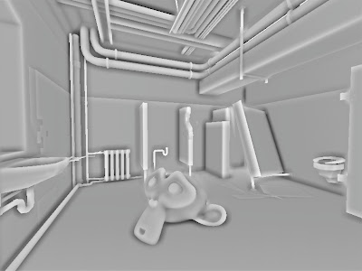
another screenshot with noise dithering and "garea = 0.4;" instead of "garea = 0.6;" to lighten scene a bit.
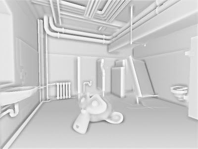
scene with and without ssao:

glsl frag shader HERE
and blend file HERE
original technique is HERE by Arkano22.
I tuned it up a bit adding my circular texture sampling and pattern sample filtering.
Right now it is the best depth-only based SSAO I have come across.

another screenshot with noise dithering and "garea = 0.4;" instead of "garea = 0.6;" to lighten scene a bit.

scene with and without ssao:
glsl frag shader HERE
and blend file HERE
October 13, 2011
NVIDIA FXAA
Antialiasing has been an exclusive thing for the PC gamers over the gaming consoles. Well of course if you could afford a proper GPU to play recent games in FullHD at 16xQMSAA... until now.
Recently I have been quite interested in post-process antialiasing approaches. They are really useful for deferred renderers and for lower-end PCs and Consoles as the antialiasing process is done after the rendering the scene - as a post-process filter, just like a color correction, SSAO, Depth of Field and HDR filters.
I first stumbled upon something that tried to imitate antialiasing was in Crysis - they extracted the edges of the rendered image , blurred the rendered image and mixed the unblurred and blurred image with edges as a mask. Since then over the time the quality has increased so much that post-process AA techniques are comparable to real antialiasing. Here are more popular ones I found: NFAA, DLAA, SSAA, MLAA, SRAA, SMAA, GBAA, GPAA and SDAA... yeah there are a lot of techniques to choose. I personally really like Humus techniques (last 3), but unfortunately they require additional buffers which I cannot access in BGE right now. But few of these techniques does not require any additional buffers at all, some of them uses depth buffer and normal buffer to find the edges.
Today I have here another post-rocess antialiasing approach - FXAA by Timothy Lottes at NVIDIA.
"Fast Approximate Antialiasing" is a new anti-aliasing technique, based on several existing anti-aliasing techniques, including MLAA. FXAA is being used in Battlefield 3, DeusEx:HE, F.E.A.R.3 .
I really like FXAA because it requires only the rendered scene buffer as input and it is really simple to integrate in any game engine.
comparison shots by the Timothy himself from TheForceUnleashed2:
http://timothylottes.blogspot.com/2011/04/nvidia-fxaa-ii-for-console.html
screenshots from BGE:
without FXAA:

with FXAA
glsl fragment shader HERE
blend file for Blender 2.5x HERE
button 1 - disables FXAA
button 2 - anables it
Recently I have been quite interested in post-process antialiasing approaches. They are really useful for deferred renderers and for lower-end PCs and Consoles as the antialiasing process is done after the rendering the scene - as a post-process filter, just like a color correction, SSAO, Depth of Field and HDR filters.
I first stumbled upon something that tried to imitate antialiasing was in Crysis - they extracted the edges of the rendered image , blurred the rendered image and mixed the unblurred and blurred image with edges as a mask. Since then over the time the quality has increased so much that post-process AA techniques are comparable to real antialiasing. Here are more popular ones I found: NFAA, DLAA, SSAA, MLAA, SRAA, SMAA, GBAA, GPAA and SDAA... yeah there are a lot of techniques to choose. I personally really like Humus techniques (last 3), but unfortunately they require additional buffers which I cannot access in BGE right now. But few of these techniques does not require any additional buffers at all, some of them uses depth buffer and normal buffer to find the edges.
Today I have here another post-rocess antialiasing approach - FXAA by Timothy Lottes at NVIDIA.
"Fast Approximate Antialiasing" is a new anti-aliasing technique, based on several existing anti-aliasing techniques, including MLAA. FXAA is being used in Battlefield 3, DeusEx:HE, F.E.A.R.3 .
I really like FXAA because it requires only the rendered scene buffer as input and it is really simple to integrate in any game engine.
comparison shots by the Timothy himself from TheForceUnleashed2:
http://timothylottes.blogspot.com/2011/04/nvidia-fxaa-ii-for-console.html
screenshots from BGE:
without FXAA:

with FXAA

glsl fragment shader HERE
blend file for Blender 2.5x HERE
button 1 - disables FXAA
button 2 - anables it
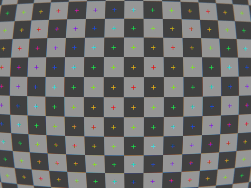
GLSL Cubic Lens Distortion
Few years ago I ported HLSL Cubic Lens Distortion shader made by a really nice guy François Tarlier. I slightly modified it, but the algorithm basically is the same one used in SynthEyes.
I encourage to visit François homepage and blog for Blender, AfterFX, compositing, VFX and mathcmoving related stuff. He is a former Environment and VFX artist at Ubisoft hehe.
Here are few screenshots of the shader in action:
undistorted:

distorted w chromatic abberration and slight blurring at edges:

lens distortion & my BPCEM reflection scene:

a screenshot in my real-time snowflake growth demo with lens distortion shader applied:

more info about the snowflake project HERE
download link to snowflake demo blend (for Blender 2.5x & 2.6x):
HERE
download link to blend file for lens distortion demo (for Blender 2.5x & 2.6x):
HERE
controls: mouse&WASD - camera movement
1 - disables the filter
2 - enables the filter
glsl fragment shader:
http://dl.dropbox.com/u/11542084/lens_distortion
I encourage to visit François homepage and blog for Blender, AfterFX, compositing, VFX and mathcmoving related stuff. He is a former Environment and VFX artist at Ubisoft hehe.
Here are few screenshots of the shader in action:
undistorted:

distorted w chromatic abberration and slight blurring at edges:
lens distortion & my BPCEM reflection scene:

a screenshot in my real-time snowflake growth demo with lens distortion shader applied:

more info about the snowflake project HERE
download link to snowflake demo blend (for Blender 2.5x & 2.6x):
HERE
download link to blend file for lens distortion demo (for Blender 2.5x & 2.6x):
HERE
controls: mouse&WASD - camera movement
1 - disables the filter
2 - enables the filter
glsl fragment shader:
http://dl.dropbox.com/u/11542084/lens_distortion
September 19, 2011
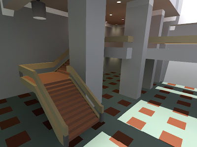
box projected cube environment mapping
I have been quite busy moving to another country, so nothing new this time. Oh, yeah, I added donate button, hehe.
BPCEM or box projected cube environment mapping is a cube environment mapping technique made by Bartosz Czuba http://devlog.behc.pl/. I thank him for helping me get this to work in BGE.
Regular Cube Environment Mapping is a very common technique of making fast fake reflections. It works best in outdoors, when reflecting distant skies and stuff that reaches to infinity, but looks very wrong in indoors, especially on flat surfaces, like walls and floor. It is caused by cube-map coordinates that reaches to infinity.
What BPCEM basically does, it takes the cube-map coordinates and clamps them to the size of the room. This technique only looks best in simple box shaped rooms. The original thread about BPCEM is HERE.
comparison stills (regular cube mapping vs BPCEM):
regular cubemap still looks fine on spheres, but wrong on flat surfaces.

All the difference makes these few lines of code:
vec3 bpcem (in vec3 v, vec3 eMax, vec3 eMin, vec3 ePos)
{
vec3 nrdir = normalize(v);
vec3 rbmax = (eMax - pos)/nrdir;
vec3 rbmin = (eMin - pos)/nrdir;
vec3 rbminmax;
rbminmax.x = (nrdir.x>0.0)?rbmax.x:rbmin.x;
rbminmax.y = (nrdir.y>0.0)?rbmax.y:rbmin.y;
rbminmax.z = (nrdir.z>0.0)?rbmax.z:rbmin.z;
float fa = min(min(rbminmax.x, rbminmax.y), rbminmax.z);
vec3 posonbox = pos + nrdir * fa;
return posonbox - ePos;
}
here is GLSL code: http://dl.dropbox.com/u/11542084/bpcem
and a .blend file: http://dl.dropbox.com/u/11542084/bpcem_playground.blend
August 8, 2011
volume ray casting in BGE
Hey, I got volumetric ray casting to work in Blender Game Engine. The shader is fully done in GLSL, including front&back face calculation in single pass and 2D texture conversion to texture3D, so it should be reeaally easy to implement in every OpenGL supporting engine.
The blend. file is here:
DOWNLOAD
volume texture:
DOWNLOAD
glsl fragment shader: (might crash on ATI/AMD gpu`s. debugging in progress..)
DOWNLOAD
screenshots taken in BGE (click on the thumbnails to see them full-sized) :

different opacity values

simple sample dithering

The blend. file is here:
DOWNLOAD
volume texture:
DOWNLOAD
glsl fragment shader: (might crash on ATI/AMD gpu`s. debugging in progress..)
DOWNLOAD
screenshots taken in BGE (click on the thumbnails to see them full-sized) :

different opacity values

simple sample dithering

Subscribe to:
Posts (Atom)